Electronic circuits from VHDL programming
Posted: Fri Nov 11, 2016 10:57 pm
VHDL (VHSIC Hardware Description Language) is a hardware description language used in electronic design automation to describe digital and mixed-signal systems such as field-programmable gate arrays and integrated circuits
https://en.wikipedia.org/wiki/VHDL.
I think, Tanzanian electronics students should try this. May be in their final year projects, they may simulate their designs and present to their teachers rather than just implementing the hardware part of the project in PCB boards.
You can download WebPack version for free in Xilinx website below. Most of the IC's, boards have inbuilt HDL.
https://www.xilinx.com/products/design- ... bpack.html
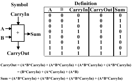
I have written the code to create a schematic of a full adder in HDL that can be uploaded to FPGA board. Students may follow the procedures in my video to make different electronic circuits and simulate their code. You just need to know logics SOP( Sum of products) to start with. With this software, you can also create schematic and produce VHDL from your schematic.
Truth table:

Series 5 FPGA

Create half adder, 7 Segment display circuits etc.
https://en.wikipedia.org/wiki/VHDL.
I think, Tanzanian electronics students should try this. May be in their final year projects, they may simulate their designs and present to their teachers rather than just implementing the hardware part of the project in PCB boards.
You can download WebPack version for free in Xilinx website below. Most of the IC's, boards have inbuilt HDL.
https://www.xilinx.com/products/design- ... bpack.html
I have written the code to create a schematic of a full adder in HDL that can be uploaded to FPGA board. Students may follow the procedures in my video to make different electronic circuits and simulate their code. You just need to know logics SOP( Sum of products) to start with. With this software, you can also create schematic and produce VHDL from your schematic.
Truth table:

Series 5 FPGA

Create half adder, 7 Segment display circuits etc.